


ใครที่สนใจ IOT ( ทุกอย่างเป็นInternet)ไม่รู้ว่าจะเริ่มอย่างไร มองไปทางใหนก็ยากไปหมด ลองใช้ APP Inventor ดูครับ น่าสนใจดี ง่าย ๆ ตามตัวอย่างนี้ ควบคุมการปิดเปิด อุปกรณ์ไฟฟ้า และ หลอดไฟ แบบพื้นฐาน การประยุกติ์ ขึ้นอยู่กับผู้ใช้ครับ

สิ่งที่ต้องจัดเตรียมดังนี้ครับ
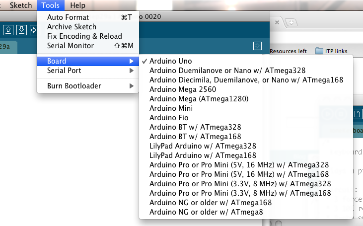
1. โปรแกรม Arduino IDE หา Download ได้ จาก Arduino.cc ใช้สำหรับโปรแกรม Node MCU

2.Board Node MCU ESP8266 แนะนำใหม่สุด V3. หาได้ตาม ร้าน Arduino ทั่วไป
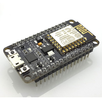
หมายเหตุ ยังมี Board ที่ใช้ CPU ESP8266 อีกหลาย ยี่ห้อ แต่แนะนำตัวนี้ เนื่องจากสะดวกที่สุด มี USB TO Serial ในตัว และ Auto program ซึ่งใช้งานสะดวกสำหรับผู้เริ่มต้นครับ
3.Google Account สำหรับ ใช้ App Inventor ใช้งาน ได้ตาม Link นี้ครับ http://ai2.appinventor.mit.edu
ปล.เครื่อง คอมพิวเตอร์ต้องติดตั้ง Java ด้วยครับ
การเขียนโปรแกรม แบ่งเป็น 2 ส่วน
1.โปรแกรมควบคุม ในที่นี้เขียนด้วย App Inventor เราจะเรียกว่าเป็น Client


ตัวอย่าง Download App Inventor กดที่ Icon ได้เลยครับ
2. โปรแกรมสำหรับ Node MCU เราใช้ Arduino IDE เขียน สำหรับการติดตั้ง Library สำหรับ Node MCU ให้ ศึกษา และ ติดตั้งตาม Link นี้ครับ http://github.com/esp8266/arduino
ส่วนนี้เราจะเรียกว่า Server

ส่วน Source Code ของ Node MCU copy ตามนี้ไปทดลองได้เลยครับ
/*
* This sketch demonstrates how to set up a simple HTTP-like server.
* The server will set a GPIO pin depending on the request
* http://192,168,1,8/gpio/0 will set the GPIO2 low,
* http://192,168,1,8/gpio/1 will set the GPIO2 high
* server_ip is the IP address of the ESP8266 module, will be
* printed to Serial when the module is connected.
* io follow gpio not d0 ---- supak 27 dec 2015
* Fix IP For test supak 27 dec 2015
*/
#include
const char* ssid = "................"; // ชื่อ Access Point
const char* password = "..............."; //password Access Point
IPAddress local_ip = {192,168,1,8}; // IP address ของ Node MCU แก้ตามเหมาะสมของผู้ใช้
IPAddress gateway = {192,168,1,1}; //
IPAddress subnet = {255,255,255,0};
WiFiServer server(80); // http port
// Create an instance of the server
// specify the port to listen on as an argument
void setup() {
Serial.begin(115200);
delay(10);
// prepare GPIO5 กำหนดขา ควบคุมค่า Output ของ Node MCU
pinMode(5, OUTPUT);
digitalWrite(5, 0);
// Connect to WiFi network
Serial.println();
Serial.println();
Serial.print("Connecting to ");
Serial.println(ssid);
WiFi.begin(ssid, password);
WiFi.config(local_ip, gateway, subnet);
while (WiFi.status() != WL_CONNECTED) {
delay(500);
Serial.print(".");
}
Serial.println("");
Serial.println("WiFi connected");
// Start the server
server.begin();
Serial.println("Server started");
// Print the IP address
Serial.println(WiFi.localIP());
}
void loop() {
// Check if a client has connected
WiFiClient client = server.available();
if (!client) {
return;
}
// Wait until the client sends some data
Serial.println("new client");
while(!client.available()){
delay(1);
}
// Read the first line of the request
String req = client.readStringUntil('\r');
Serial.println(req);
client.flush();
// Match the request
int val;
if (req.indexOf("/gpio/0") != -1)
val = 0;
else if (req.indexOf("/gpio/1") != -1)
val = 1;
else {
Serial.println("invalid request");
client.stop();
return;
}
// Set GPIO2 according to the request
digitalWrite(5, val);
client.flush();
// Prepare the response
String s = "HTTP/1.1 200 OK\r\nContent-Type: text/html\r\n\r\n\r\n\r\nGPIO is now ";
s += (val)?"high":"low";
s += "
\n";
// Send the response to the client
client.print(s);
delay(1);
Serial.println("Client disonnected");
// The client will actually be disconnected
// when the function returns and 'client' object is detroyed
}
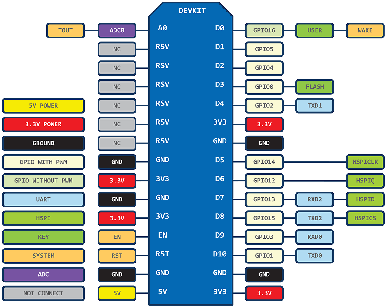
Layout Pin Node MCU ตามนี้ครับ
มีคนเขียนเรื่อง Node MCU ESP8266 ใว้มากมาย หาอ่านได้ตามอัธยาศัยเลยครับ กดตาม Link นี้เลยครับ
ท่านใดสนใจอยากรู้อะไรเพิ่มเติมก็สามารถสอบถามจาก ความคิดเห็นข้างล่างนี้ได้ครับ