


Make a Non-Contact Infrared Thermometer with IR Temperature Sensor
 IR Thermometer using Arduino and Infrared Temperature Sensor
When debugging an electronics circuit or testing a new hardware design, often times I tend to check if the components on the board are getting hot abnormally by touching them. And if something is messed up (which usually is in the first try) these components could get as hot as 80°C or more burning not only the component but also my finger along with it. After burning my fingers for more times than I could remember I decided to build my own Temperature Gun using Arduino and an Infrared Temperature Sensor. This Thermal gun will be built using a non-contact temperature sensor called MLX90614; hence it can not only be used to measure component temperatures but can also be used for measuring body temperature, surface temperature, Heat ventilation and much more. Of course, these thermal guns are readily available in the market from renowned manufacturers like Fluke, Flir etc. But they are not light on your pockets and on top of that what is more fun than building your own gadgets. So let’s get started…
Materials Required
- Arduino Pro Mini
- MLX90614 Infrared Temperature Sensor
- OLED Display – SSD1306
- Laser Diode
- 9V Battery
- Push button
- Battery Clip
- Connecting wires
MLX90614 Infrared Thermometer
Before we proceed with the tutorial it is important to know how the MLX90614 sensor works. There are many temperature sensors available in the market and we have been using the DHT11 Sensor and LM35 extensively for many applications where atmospheric humidity or temperature has to be measured. You can find some of the DIY Thermometers below:
- Digital Thermometer using LM35 and Microcontroller
- IoT Digital Thermometer using NodeMCU and LM35
- IoT Weather Station using NodeMCU: Monitoring Humidity, Temperature and Pressure over Internet
- Raspberry Pi Weather Station: Monitoring Humidity, Temperature and Pressure over Internet
But here, for a thermal gun we need a sensor that could sense the temperature of a particular object (not ambient) without directly getting in contact with the object. For this purpose we have contact less temperature sensors which utilizes Laser or IR to calculate the temperature of an object. The MLX90614 is one such sensor that uses IR energy to detect the temperature of an object. To learn more about Infrared and IR sensor circuit, follow the link.
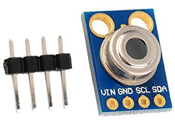
MLX90614 sensor is manufactured by Melexis Microelectronics Integrated system, it has two devices embedded in it, one is the infrared thermopile detector (sensing unit) and the other is a signal conditioning DSP device (computational unit). It works based on Stefan-Boltzmann law which states that all objects emits IR energy and the intensity of this energy will be directly proportional to the temperature of that object. The sensing unit in the sensor measures how much IR energy is emitted by a targeted object and the computational unit converts it into temperature value using a 17-bit in-built ADC and outputs the data through I2C communication protocol. The sensor measures both the object temperature and ambient temperature to calibrate the object temperature value. The features of MLX90614 sensor is given below, for more details refer the MLX90614 Datasheet.
MLX90614 Features:
- Operating Voltage: 3.6V to 5V
- Object Temperature Range: -70°C to 382.2°C
- Ambient Temperature Range: -40°C to 125°C
- Resolution/Accuracy: 0.02°C
What should be the distance between the Sensor and the Object?
One question that is not directly answered by the datasheet is the measuring distance between the sensor and the object. The value of this distance is given by the term Field of View (FOV), for our sensor the field of view is about 80°.

You can think of the sensing range to be in a conical shape from the point of sensor as show above. So, as we go far from the measuring object the sensing area increase by two folds. Meaning for every 1cm we move away from the object the sensing area grows by 2cm. In our thermal gun we have placed a laser diode on top of the sensor to know where the sensing area of the sensor is currently pointing at. I found that the values were reliable if the gun is pointed at 2cm away from the object and the accuracy goes down as we move away.
Circuit Diagram

Since the Fritzing Software did not support a part for MLX90614 sensor we have used a note to mention its connections as shown above, also we have used a red colour LED in place of a laser diode. The entire circuit is powered by the 9V battery through a push button. When the push button is pressed the 9V battery is connected to the RAW pin of Arduino which is then regulated to 5V using the on-board voltage regulator. This 5V is then used to power the OLED module, Sensor and Laser diode.
We have already learnt how to interface SSD1306 OLED with Arduino the same hardware and code will be used here. Also you can design a separate laser diode driver circuit if you require the laser beam to be more powerful.
Designing the Casing for Temperature Gun
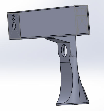
The Design Files are available for download from thingiverse; you can download the design and print one using your 3D printer or also modify it to suit your needs. The download link is given below
After downloading the files you can direclty start 3D printing the design or can do some tweaks according to your requirements.
3D printing the Enclosure:
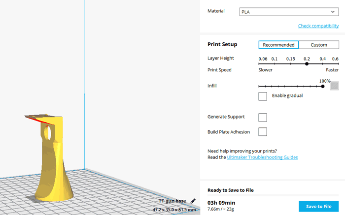
The model was then saved as STL file and converted into G-code using Cura. I used my Tevo tarantula printer to print both my parts and then screwed them together. It is also possible to print both the parts as single piece if you printer supports it. The slicing setting for my print is shown below
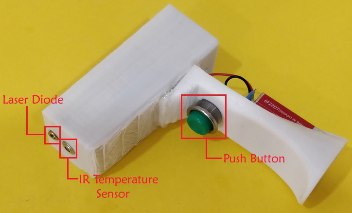
It took me nearly 6 hours to print both the parts, once printed hardware connections was made my -directly soldering wires directly to the Arduino pins using 7-pin and 4-pin Relimate connectors (RMC) for the sensor and OLED display respectively. The OLED was then mounted in the printed part using screws while the sensor and Laser diode was mounted using hot glue. The power pins (Raw, Gnd) were then slid down through a wire for the handle part which consists of the push button and battery. This wires was then connected to the battery though the push button. The Once the assembly is done the thermal gun looked like this below
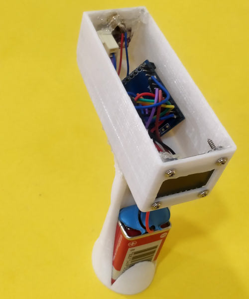
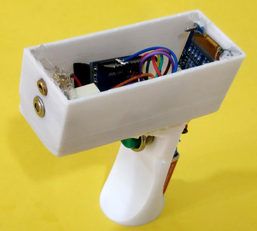
You can proceed with designing a cover for the top part, but I decided to leave it open so that I can tweak it later in future if required.
Programming for Arduino Temperature gun
The Program for Arduino should read the temperature value from the MLX90614 and display it on the OLED display. Lucky for us the program will be very simple since Adafruit has provided us a Library to easily read data from the MLX90614. The Library can be downloaded from below link
The link will download the library as a ZIP folder. After download add it to the Arduino IDE following the command Sketch -> Include Library -> Add .ZIP Library and browse for the location of this ZIP file. Also make sure you have followed OLED interfacing with Arduino tutorial so that you have installed the required libraries for OLED display module as well. Once the libraries are added we can begin our program, the complete program for this project can be found at the bottom of this page. Here the same program will be explained in small snippets.
Like always we begin the program by adding the required library files. Here the Wire library (in-built) is used to communicate using I2C protocol and the SparkFunML90614 library is used to for communicating with the sensor. The SPI, GFX and SSD1306 libraries are used for communicating with 4-wire SPI protocol to the OLED display module.
#include <Wire.h>
#include <SparkFunMLX90614.h>
#include <SPI.h>
#include <Adafruit_GFX.h>
#include <Adafruit_SSD1306.h>
We then define the pins of the OLED display to which we have made the connection. Since the module works with SPI we have used the SPI pins of the Arduino. There are OLED displays that works with I2C protocol as well, but we can’t use them here since the I2C pins are already occupied by the thermometer sensor.
#define OLED_MOSI   9
#define OLED_CLK   10
#define OLED_DC    11
#define OLED_CS    12
#define OLED_RESET 13
Adafruit_SSD1306 display(OLED_MOSI, OLED_CLK, OLED_DC, OLED_RESET, OLED_CS);
Inside the void setup() function, we initialize serial monitor for debugging and also the IR temperature sensor using the object therm that we created earlier. Here in India the most followed unit for temperature is Celsius (degree C) hence we have set the unit of the with TEMP_C you can also change this to TEMP_F if you need the values to be in Fahrenheit (F). Finally we initialize the OLED display and clear its display. Also the screen of OLED is rotated by 180 degree for easier mounting option in the casing.
void setup()
{
  Serial.begin(9600);
  therm.begin();
  therm.setUnit(TEMP_C);

   display.begin(SSD1306_SWITCHCAPVCC);
   display.clearDisplay();
   display.setRotation(2);
}
Inside the loop function, we read the value of temperature from the sensor and convert it into String to be displayed in the OLED display. We have also printed the value on the serial monitor for debugging purpose. We have also incremented a variable called runner which is produce a small animation on the screen every time the value of the temperature sensor is updated successfully, this will help us know if the reading is stuck for some reason.
  if (therm.read()) // On success, read() will return 1, on fail 0.
  {
    temperature = String(therm.object(), 2);
    Serial.print("Object: ");
    Serial.print(temperature); Serial.println("C");
    display.clearDisplay();
    runner++;
    delay(5);
  }
Testing Arduino Thermal Gun
Once the Arduino code is ready we can upload it to our hardware using an external TTL programmer or FTDI board since the pro mini does not have one on-board. Then simply press the push button to trigger the thermal gun and you will notice the laser beam falling on the object and the temperature of the object being displayed on the OLED screen as shown below. Here I have used it to measure the temperature of a component as pointed by the laser beam.
The thermal gun was also tested on soldering iron, 3D printer nozzle, ice cubes etc and a satisfactory result was observed. The complete working of the thermal gun can be found in the video at the bottom of this page. Hope you enjoyed the project and learnt something useful in building it, if you have questions leave them in the comment section below or use our forums for more technical questions.
/***********************************
Arduino Contactless thermometer
MLX90614 I2C connection
OLED 4-wire SPI connection
Dated: 7-6-2019
Code by: Aswint Raj
**********************************/
#include <Wire.h>
#include <SparkFunMLX90614.h>
#include <SPI.h>
#include <Adafruit_GFX.h>
#include <Adafruit_SSD1306.h>
// If using software SPI (the default case):
#define OLED_MOSI 9
#define OLED_CLK 10
#define OLED_DC 11
#define OLED_CS 12
#define OLED_RESET 13
Adafruit_SSD1306 display(OLED_MOSI, OLED_CLK, OLED_DC, OLED_RESET, OLED_CS);
IRTherm therm;
void setup()
{
Serial.begin(9600);
therm.begin();
therm.setUnit(TEMP_C);
display.begin(SSD1306_SWITCHCAPVCC);
display.clearDisplay();
display.setRotation(2);
}
String temperature;
char runner;
void loop()
{
if (therm.read()) // On success, read() will return 1, on fail 0.
{
temperature = String(therm.object(), 2);
Serial.print("Object: ");
Serial.print(temperature); Serial.println("C");
display.clearDisplay();
runner++;
delay(5);
}
display.setTextSize(2);
display.setTextColor(WHITE);
display.setCursor(display.width()/4,display.height()/12);
if (therm.object()>=100)
display.setCursor(display.width()/4,display.height()/12);
display.println(temperature);
display.drawLine(display.width()/runner,display.height() - display.height()/2.5, display.width()/runner+1, display.height() - display.height()/2.5, WHITE);
display.setCursor(0,display.height()-display.height()/4);
display.setTextSize(1);
display.println(" Arduino Thermlgun");
display.setCursor(display.width()- display.width()/4,display.height()/12);
display.println("deg C");
display.display();
if (runner>20)
runner=0;
}